Tuesday, December 1, 2009

Corrective Surgery

So it's been a while since I updated... Yeah.

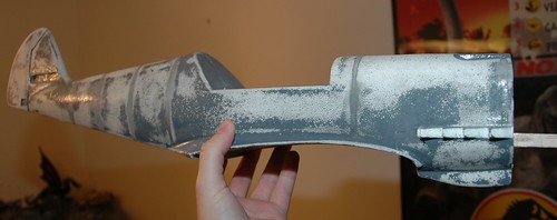
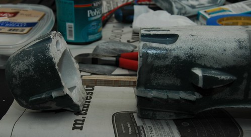
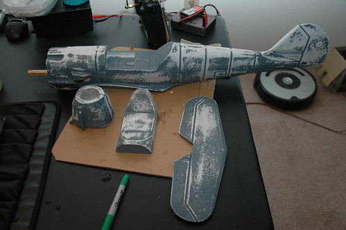
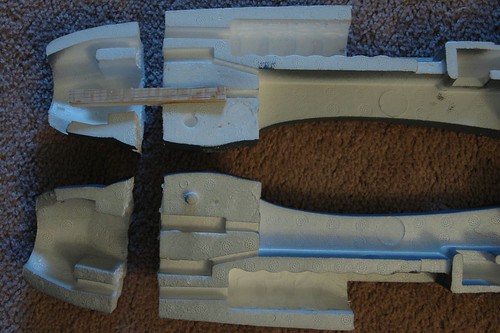
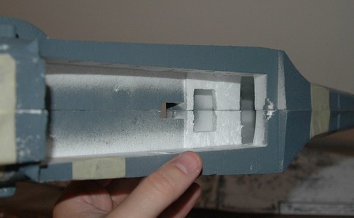
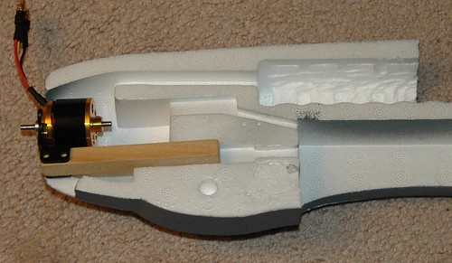
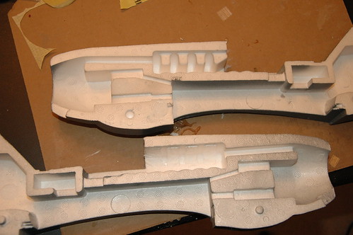
Well, I finally got around to doing some more work on the plane, the next task was to re-attach the nose that I so callously cut off so that I'd have access to the motor mount once the plane was all glued together.

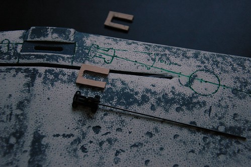
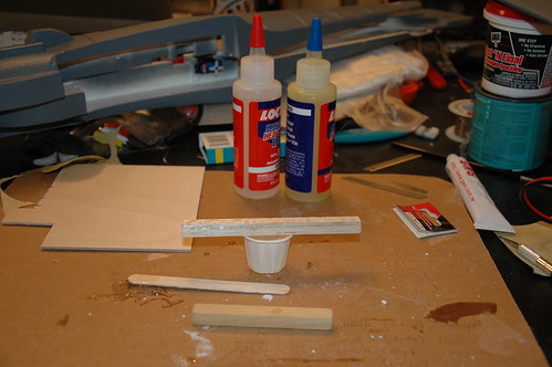
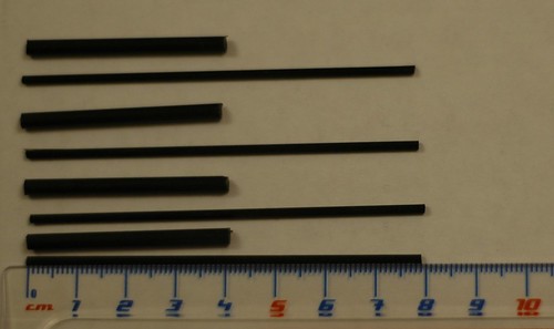
First, thing I went and bought some carbon-fiber rods (1.8mm diameter I believe) and some carbon-fiber tubes (with an inner-diameter of 1.8mm to match the rods) that would slot inside of each other.

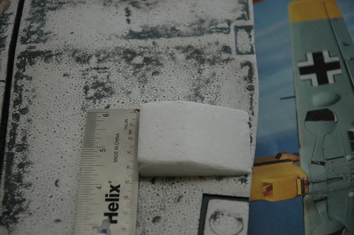
Then I proceeded to cut them up. The tube that the rods would slip into got cut to about 4cm, and the rods to about 8cm (twice the depth of the tubes). I figure this should give me plenty of strength and space to work with when I'm sliding the nose on and off, without having the rods or tubes long enough that they'd poke through the cowling of the plane.

Some Carbon-Fiber rods and tubes

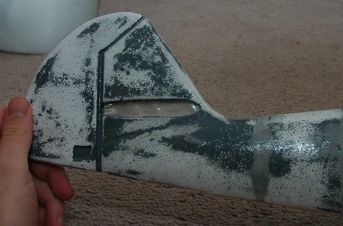
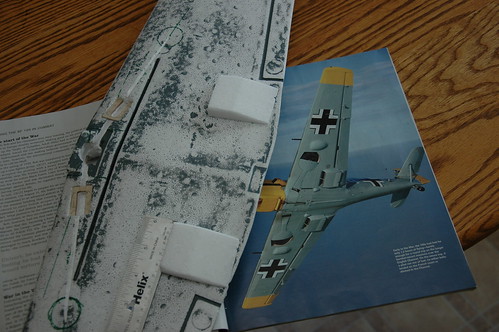
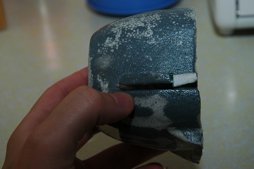
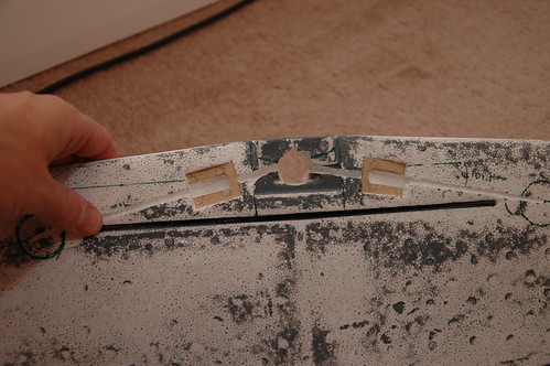
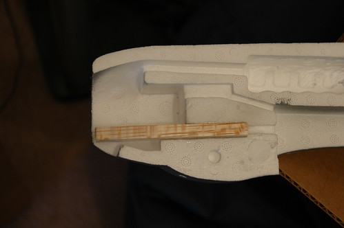
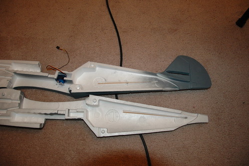
The next step was to mark the points where I wanted to put the rods (on the cowling ). I marked the cowling first because it has the least amount of excess foam, and so would be trickiest to get the rods in safely.

From those marks I extrapolated out to the edges of the plane, held the cowling flush with the fuselage and marked the same points on it, and then extrapolated back inwards to get the point on the fuselage that would be around the same spot. It was hard to check if it was correct or not, but it turns out this worked pretty well.

Marked off the tube and rod locations

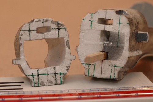
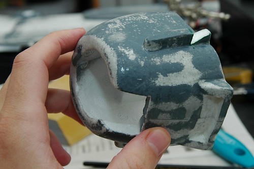
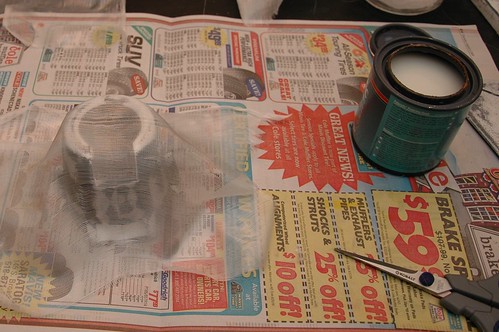
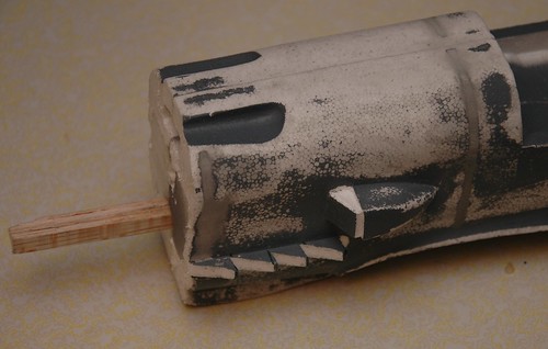
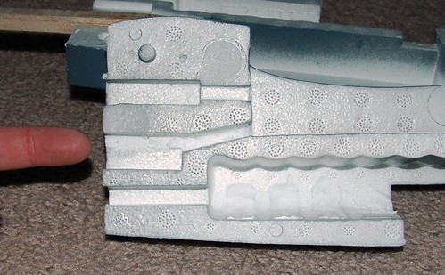
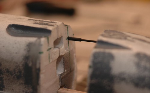
Next step was to grab a little drill bit (actually just smaller than the rods) and drill a guide hole into the cowling for the carbon fiber rods. I drilled the holes by hand because it's pretty delicate work and I needed to take my time and make sure I didn't end up drilling out the side of the cowling.

Drilling a hole by hand

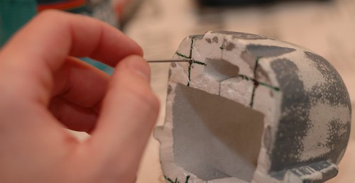
Once that was done, I test-fit the rod in the hole to make sure it looked pretty straight. Success!

First rod in its hole

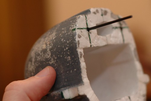
I repeated the process 4 times until all of the carbon fiber rods had nice little holes to poke into.

Repeat x4

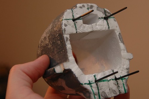
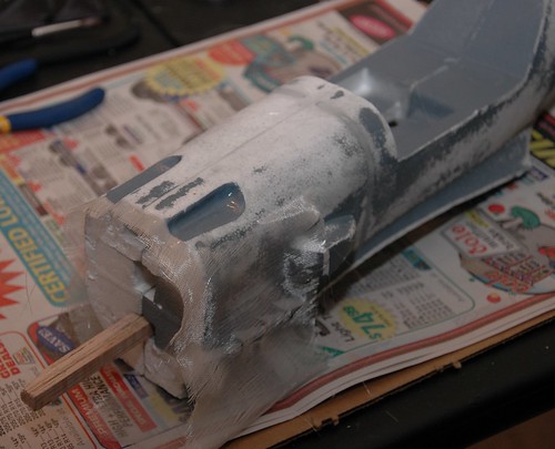
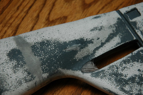
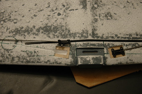
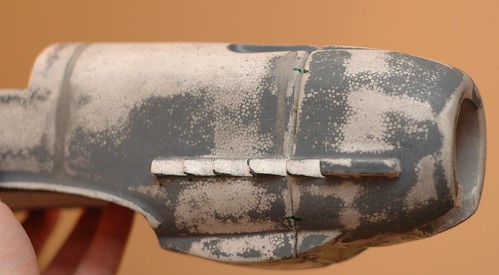
Then, I did the same thing (with a slightly larger drill bit) for the 4 tubes in the fuselage half.

And then do the same for the tubes

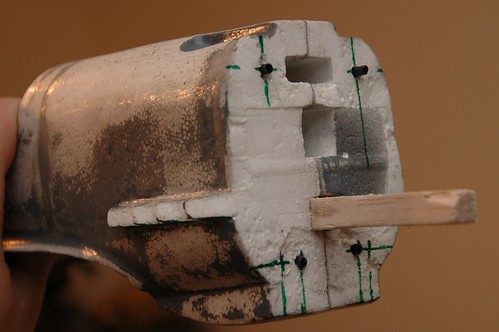
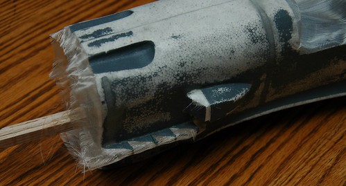
A quick test-fit with one rod and tube...

Test fitting the tubes and rod

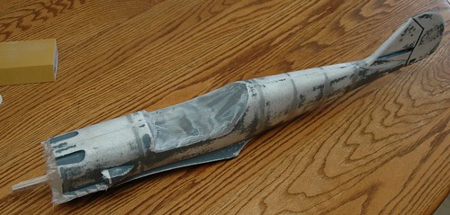
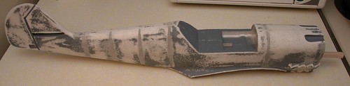
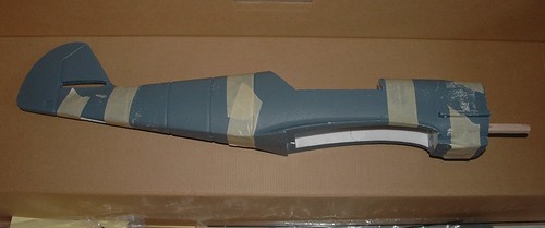
... and then give it a shot with all 4.

Get everything lined up

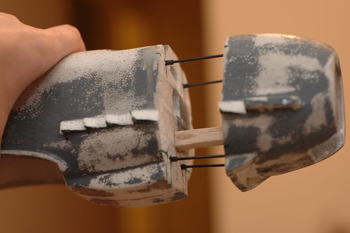
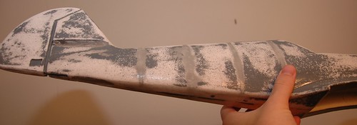
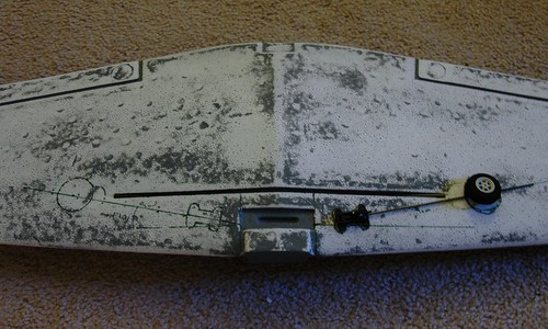
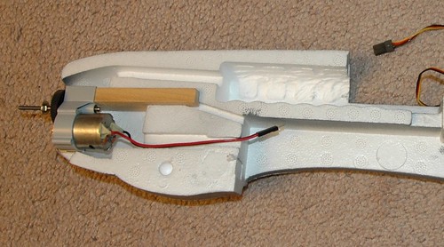
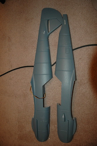
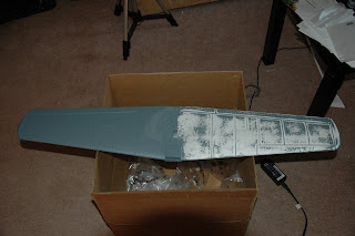
Next thing you know, the plane has a nose again!

It's got a nose again!

Now all I have to do is glue these things in there to make it nice and permanent... But it's too late to do that tonight, but soon.

Some tips that I picked up:
  • I had to shave about 1cm off of the rods before they would go into the tubes smoothly. I think they ended up a bit long because the drill bit I had was too short to get all the way into the cowling. Probably a good thing since I think I was really close to the other side... I might make the rods a little shorter (about 7cm instead of 8cm).
  • Getting the rods to slot into the tubes is a little tricky. It helped a ton to file the tips of the rods that would go into the tubes down so that they were a little pointed. It doesn't have to be sharp, just enough that they are guided into the tubes from a rounded end.
  • Take your time drilling, and do it by hand. Make sure the holes are nice and straight and it will all work out.

Sunday, October 18, 2009

(more) Fiberglassing

So I've spent some more time fiberglassing the main fuselage. Here are a couple of pictures where I'm trying to show the finish on the body (it's tough to get a good shot of it).

Fiberglassed

Fiberglassed

I covered over the hole where the vertical stabalizer is going to go, but I'll cut it out and sand it down before I actually put it in there.

Tail fiberglass detail

Here's the final finish on the engine nacelle (its just about ready for paint). You can also see a small divot I cut out of the bottom that will be painted to look like the air intake vent on the real plane (instead of the smooth lip they had there in the original model).

Cowling fiberglassed

The next step will be fixing these two peices back together I think...

Just need to fit these together

Wing Radiators

One of the distinguishing features that is missing from the original GWS 109 model is the under-wing radiators. I decided that I'd give making some a shot. I had a peice of packing foam that was about the right size, and after examining some reference photos that I had I carved some squares out.

DSC_9823

DSC_9820

I haven't attached them to the wings permanently yet, since I want to do it after I put the fiberglass on it. I'm probably also going to trim them down a little bit to keep them from interfering with the aerodynamics of the wing too much.

Fiberglassing!

So progress continues, but slowly. I did some work on the plane during some time I took off a few weeks ago, I'll let the pictures do the talking.

Laying on the fiberglass sheet

First thing I started on was putting some fiberglass on the detached section of the engine cowling. This was the first fiberglass I've ever tried to apply, and all things considered I think it went pretty well. I used 0.75oz fiberglass cloth and Minwax polycrylic.

Fiberglass'd

DSC_9342

In the picture above, you can see the texture that the fiberglass adds to the nosecone. After letting the nose cone dry for a few hours I would apply another layer of minwax to fill in the weave of the fiberglass. The next day I sanded and did another layer of minwax.

Next I moved on to fiberglassing the fuselage.

Glassing the fuselage

DSC_9827

DSC_9825

I followed the same basic process (two coats of minwax on the first pass, then sanding and some more) for the fuselage. In the next shot you can see the way that I covered the control rod tubes. I'm hoping that they'll blend into the body a little bit and not be so obvious.

DSC_9826

Next, building the wing radiators...

Monday, September 21, 2009

Aerial Photo

Taken from my plane with my camera onboard. Kind of neat. Its the building where I work.

Aerial Panorama

Monday, August 31, 2009

Spackl'd

Got the fuselage all spackled up. Took two coats of spackle because the lines are a pain to get filled right.

Spackled Fuselage

I also took the time to cut the radiator a little nicer (it's actually two interlocking pieces in real life) and got the fins for the engine exhaust cut.

Cut the radiator and the exhaust ports

I also got the vertical stabalizer spackled, and the cockpit, but I don't have a picture.

Next up: Fiberglass!

Retracts Part 2/?

Okay, so I managed to get some more progress on the retractable landing gear front, and boy, am I surprised its all working out.

First thing I cut out some channels for the servo arms to run to the retracts positions and hollowed out a little hole for the servo itself. Right now everything is fit for an HS55 servo, which may or may not give me enough throw to fully retract the gear... I'm going to test this of course before I finally mount everything, but since any other servo is going to be bigger than the HS55, I figured fitting it first would be OK.

Channels for retract arms mostly cut

Next I flipped the wing over and cut a hole to counter-sink the servo into the top of the wing. I need to do this for two reasons:
  1. it gets the servo head level with the retract mechanism
  2. It gets the servo out of the way of the ESC that is going to be mounted right above it in the fuselage cavity. I'm really glad I noticed this before I actually started gluing things!

A servo test fit for the retracts

Here's some more pics of how it fits together:

Servo out of its hole

Servo from the top

Going to put the retracts aside for a bit. Next step, spackle the fuselage.

Oops

I just realized I never put up a picture of the fuselage all glued together, so here ya go:

Fuselage, tail, cockpit all sanded

I also finished sanding them all up so the pieces are ready to be spackled now...

(I'm actually playing catchup with these posts, so forgive me if things don't make a whole lot of sense all the time)

Monday, August 17, 2009

Installing Retracts (part 1 of many)

First off, this is by FAR the scariest part of the build so far. I'm absolutely terrified of cutting into the wings of the plane. The practice I had cutting out various bits of foam in the last step certainly helped me get the confidence up though.

I've somehow gotten it into my head that I need retractable landing gear (probably something to do with being totally awesome). So the next step in the build involved a lot of planning (i.e. holding the wing and trying to figure out how it was all going to work) and waiting for the retracts I ordered to arrive.

When they finally showed up, I spent some more time thinking about how I was going to mount them and decided I would need to build something to screw them in to. First, I used the actual retracts to trace out the outlines of where I wanted the retracts to go using a marker. This let me get an idea of how it would all go together. Next I cut the little mounting platforms out of some aircraft plywood I had left over from a previous project.

Retracts before installation

Next came the scary part: Actually mounting them in the wing. First I cut a depression in the wing that the mounting platforms could sit in, and made sure it was snug. It helped to trace the wood with the Xacto knife rather than trying to measure it and get everything lined up that way. Then I had to hollow out some more of the wing to allow the retract mechanism to function.

To do this, I used both the Xacto knife (to cut the sides of the cavity) and then the dremel (to hollow it out and do more serious material removal). I ended up with a ton of tiny styrofoam particles and a little hole in the wing.

A side note: I found it best to run the dremel on its slowest setting with a straight edged rotary cutter (since I didn't have a grinding bit like other people I've seen). The straight edge helps a LOT when carving out sides of the cavity. The only other trick is to go slow and be careful, the dremel will sink through the foam like it wasn't there, so make sure you're holding steady.

I kept going, test and testing and testing after almost every cut. One of the hardest parts is making sure the two sides of the gear are at the same angle. (We'll see how I did when it comes time to hook some actual wheels up to this thing.) I'm hoping I can fix any little errors when it comes time to actually glue the retracts into the wing.

Retracts hollowed and test-fit

At the end of the operation I had a both retracts (almost) mounted in the wing, but there's still a lot of work left to do.

Building The Fuselage

So when last I left off, I had just test-fit the newly minted stick-mount for the brushless motor.

The next step was to actually glue that sucker in there, and after reading a bunch of forum posts about getting the engine mounted right (thrust angles!) I decided to bite the bullet and glue that sucker in. I ended up using the same angle that the instructions recommend (I think its 2 degrees to the right) and mounted it pointing a bit down. Hopefully that'll be enough of an angle to offset the torque from the motor. We'll just have to wait and see when I maiden it.

Engine mount glued

But wait! Thats not all! On Saturday, I decided to get off my duff and do some more work. *Gasp*

I'd received the retracts that I'd ordered on Friday, so I set about planning on how to mount them. After much referring to various pictures and looking for examples on the web I marked off the position of the wheels and mounts. I also took the opportunity to glue in the wing-spar. I used a hollow carbon-fiber tube that I have on hand (I'm going to use them to attach the engine nacelle later) instead of the pole that came with it (since the carbon-fiber is lighter).

Wing spar and some planning

The thought of cutting into the wing absolutely terrified me, so I promptly set that aside and set to work on something a lot less scary.

The modification I had originally planned to make to the fuselage before it got glued together was to modify the engine nacelle so that it was detachable. This will make getting to the engine a lot easier [read: possible] and is a pretty popular modification for this model.

I was humming and hawing about whether to cut the nacelle off before or after I glued it, and decided to do it before. I was a bit sloppy with the Xacto knife, but I think it wasn't too terrible. I'm hoping to be able to clean it up a little when I mount it back on the fuselage (with a little help from my good friend Mr. Lightweight Spackle and Mrs. Sandpaper).

Nacelle detached

After cutting the nacelle off, I decided that I might as well give the motor and ESC a test-fit to make sure everything was going to meet up in the right places before I glued it all together. Boy am I glad I did! It turns out that the wires on the ESC and the motor were just a little too short (because I had to mount the motor out a little further than originally planned). Since I hadn't glued the whole thing together yet I was able to fix the problem by enlarging the wire channel from the nacelle a bit. This would have been a HUGE pain if I had already glued everything together.

With my trusty Xacto knife I managed to do quite a nice job straightening out the channel to give myself that tiny little bit of extra space that would allow me to mount the ESC right up front.

Enlarged Channel For ESC wires

It was right before I reached for the glue (for the second time) that I remembered something I'd seen on a 109 build thread about a different way to mount the aileron servos (instead of the double-sided tape the instructions mention). So, I whipped out the Dremel and the Xacto knife and made myself a little tray for the aileron and rudder servos. I had to shave off a little of the foam in the fuselage to keep them the same height as they would have been before, but since I hadn't glued the fuselage together yet it was really easy.

Servo Tray

There are two reasons I can think of to mount the servos this way: 1) This fixes them more tightly in place (they don't flex at all because they're screwed into the wood) and 2) I can more easily change the servos if anything goes wrong.

With all of that done, it was time to bite the bullet and glue that bad boy together:

Fuselage Glued

Here's the nacelle all glued and taped up:

Engine Nacelle Glued

I haven't actually mounted the little servo tray yet, but here's a shot of where it will go (you can see where I cut away enough foam to keep them mounted in the original position).

This is where the servo tray goes

Next stop: Retractville

Monday, August 10, 2009

Dried

Here's a picture of the modified engine mount, all dried up and in place (not glued yet).

New Stick Mount

As you can see I'm going to need to trim a bit off the end to keep it from sticking into the prop, but that'll be easy with a lil' hacksaw lovin'.

I think that's the only thing I really wanted to be sure of before I glued the fuselage together. I'm going to read up on what the angles/position of the engine should be before I do anything though...

Engine Arrived!

My new brushless engine for the Me109 arrived today! I'm impressed with how fast it shipped, I ordered it at the end of the day thursday and it showed up at work just before noon. Yeay for the internet and shipping.

Engines and props for the 109

Here's the kit I bought (all of it was from innov8tiveDesigns.com, which I heard about on ATTF Podcast) :
As you can see from the pictures above, the ESC and Motor came in some bitchin' metal cases, I was very impressed with the presentations.

Now that I have the engine, I decided to see how it would fit. Good lord am I glad I didn't start gluing things already. You can see from the next two pictures that I'm going to have to mount the engine in the reverse orientation. Instead of having the stick mount on the top of the engine nacelle, I'm going to have to flip it around and mount it on the bottom (since there's no gearbox and the spinner needs to be in the middle of the model).

Original Engine Mount

Brushless Engine Mount (stick too short)

That's all well and good, except that, as you can see from the pictures, in order to get the engine far enough forward to spin the prop in front of the nacelle, I'm going to need to pull the stick WAAAAY out of the housing. So far out in fact, that I'm terribly worried it wouldn't be enough foam to hold the engine safely. So what am I going to do? Well, I rummaged around in a bag of spare balsa wood peices that I had lying around, and managed to find some bits that I can epoxy together to make a longer stick mount. It turns out that they're the perfect size once they're glued together.

Epoxy is the answer!

I'm going to let the epoxy dry overnight, and might give it another go tommorow after work. Here's hoping everything goes better next time.

Also, I need to clean my table.

Sunday, August 9, 2009

Little progress

I was planning on working on the fuselage yesterday, but after planning a bit, I think I'm going to wait until I get the rest of the power system (engine, speed controller, prop, etc..) that I ordered. I want to make sure it fits before I seal up the fuselage, which I'm hoping will save me some trouble.

So, instead I decided to do what I could and install the guide-tubes for the rudder and aileron into the fuselage halves. This had to be done before I could seal the fuselage anyway, and doesn't depend on the power system at all.

Guide tubes installed

Guide tubes installed

I'm going to modify the engine nacelle so that its removable, but that's going to wait for another day. I can still sand and spackle the fuselage, but I would really like it to be assembled before I do that, so I know the pieces are fitting together nicely.

I also went ahead and enlarged the battery compartment, it was made for NIMH battery packs, and I'm going to be running off of lipo, so it needed to be trimmed back a bit. I'm going to test-fit my batteries before I seal it up, and probably add some fuzzy side of velcro to the top and bottom to make sure its all snug when there's a battery in there.

Making space for the battery

Saturday, August 8, 2009

It begins!

I've spent a lot of time since I got my plane earlier in the week planning things out (I probably spent MOST of the week looking for pictures of 109's and looking for paint schemes I want to do).

I grabbed a couple reference pictures of the paint-job I wanted to do, and found an old magazine that I had with a ton of great photos. I think that should be enough for me to figure out the paint scheme. I'm going to have 'fun' figuring out the exact paint colors I'm sure...


I found a few threads on building GWS foamies that I'm leaning heavily on for instructions:
After reading through a bunch of posts on these threads and looking very carefully at the various pictures, I decided I might as well get started.

Since I want to get this plane close to the real version, I wanted to take out the panel lines that GWS has etched into the model when you buy it new. That means spackling up the lines and lots of sanding.

Since I got the pre-painted version, it was a bit of a pain to sand (the paint kept binding up the 320 grit sandpaper I have), so I ended up doing it wet (running it under the tap while I sanded). I used my finger and a piece of cardboard from an old cereal box to smooth out the lines as I filled them.


I tested it out on just a portion of the wing first, and you can see in the picture how I ended up sanding most of the paint off when I sanded the spackle. I ended up going through and sanding off the rest of the paint and the fake 'bolts' that are on the wing before I did the rest of the spackling.

I let it sit overnight, and sanded it all down the next morning. I had to do this twice because I had a little trouble getting the spackle to fill the lines and not pull out after I'd done it. Right now I have the top of the wing finished, and am ready to do the bottom.